Overview
This post explains how I performed tests on my miata’s fuel injectors. It takes a DIY approach to test equipment, but does require that you have an after-market ECU that lets you put the fuel system in a test mode. In my case, I have a Megasquirt ECU which has an injector & ignition test mode.
I first came up with this test setup a few years ago when I was working on my rotary miata and didn’t know what size injectors it had. I’m writing this post now because I’ve been having spark plug fouling issues on cylinder 4 of my turbo miata, and want to see if it’s a stuck or failing injector.
Building The Test Jig
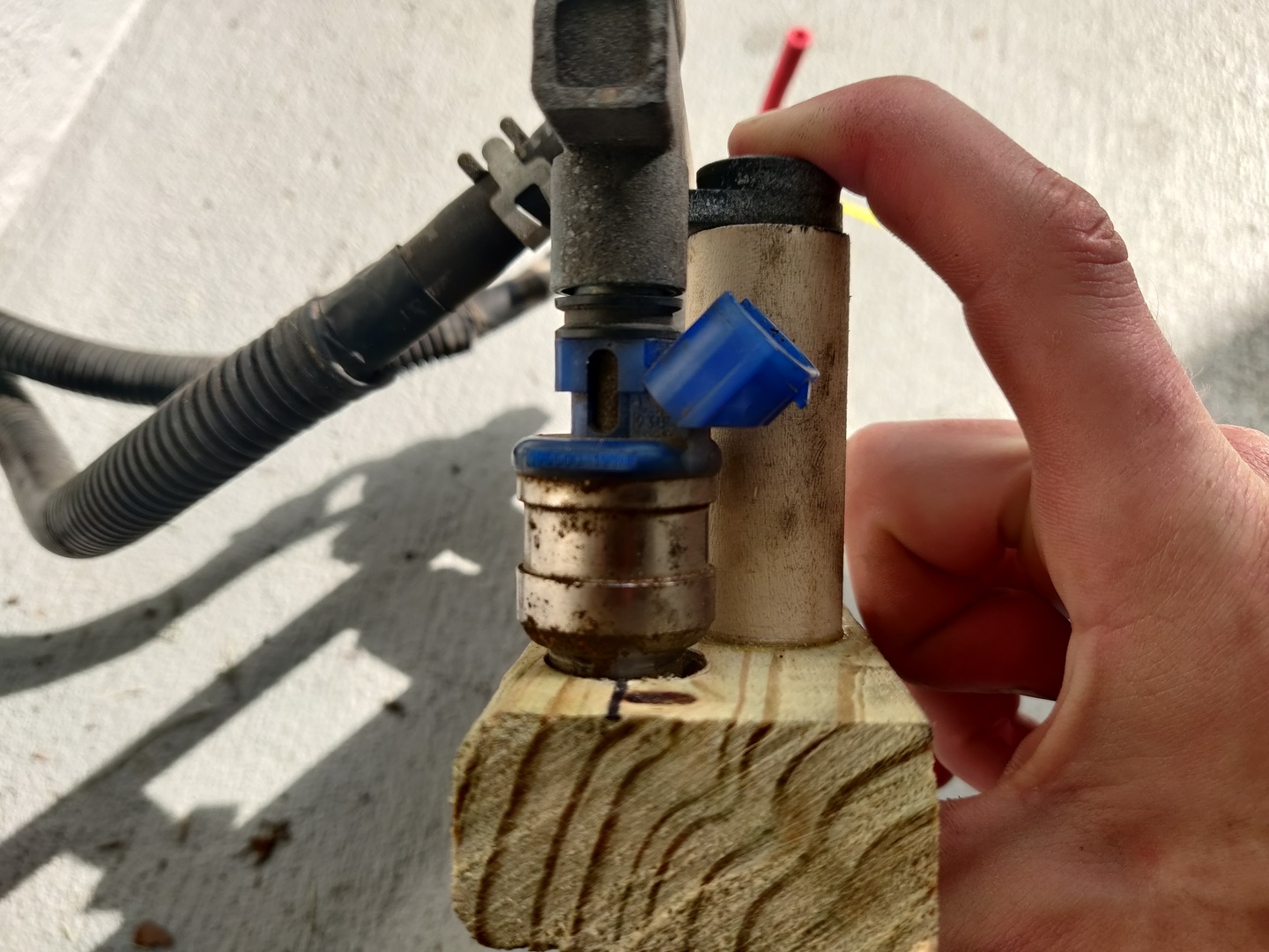
We’ll need a way to remove the fuel rail from the intake but still be able to hold the injectors into the rail while the fuel system is pressurized. The final jig will look like this.
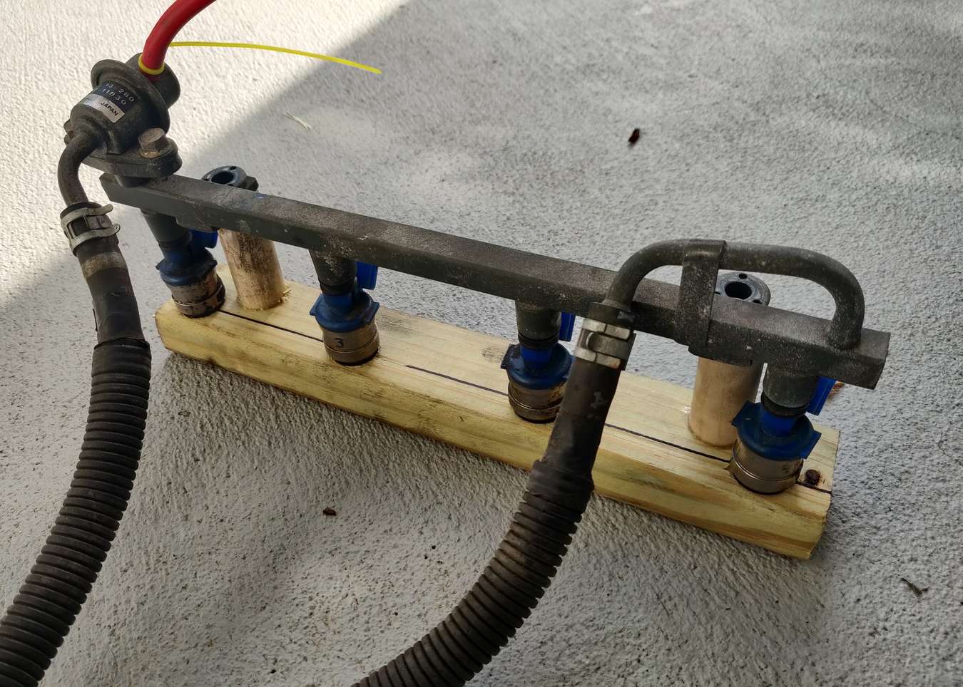
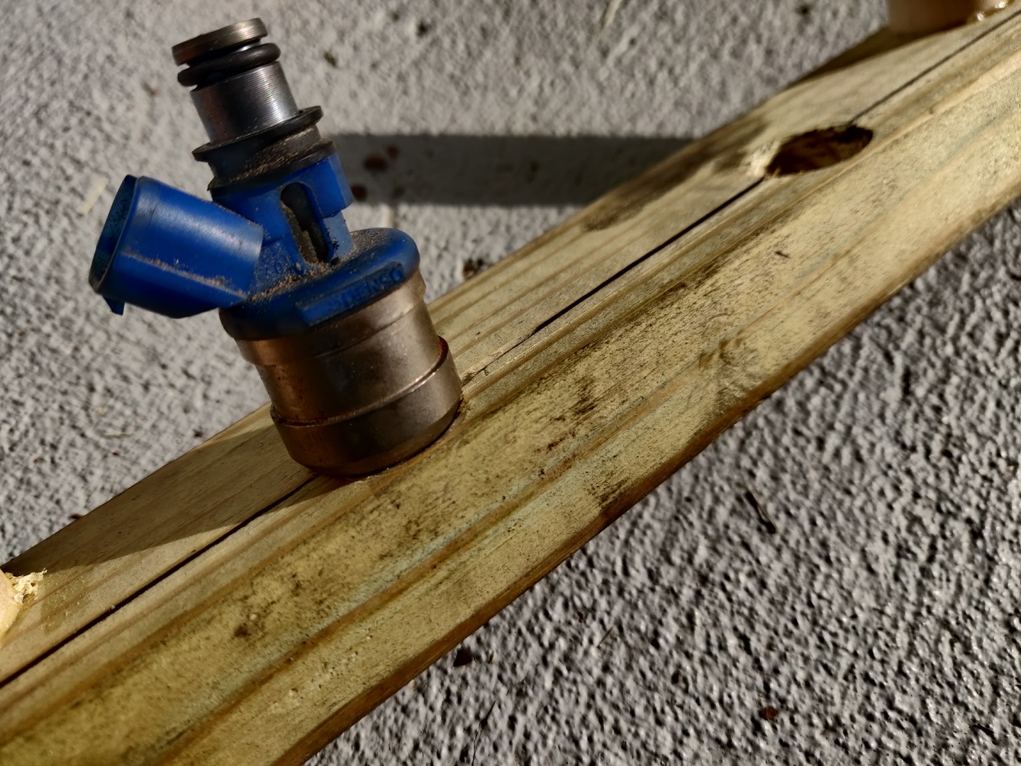
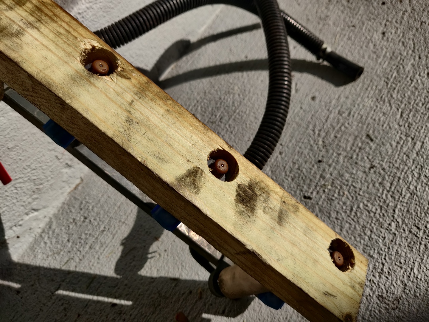
I started with a piece of 2x4 that I drilled 4 holes in for each of the injectors. The holes were large enough to hold the injectors snuggly, but not large enough to let them completely slip through.

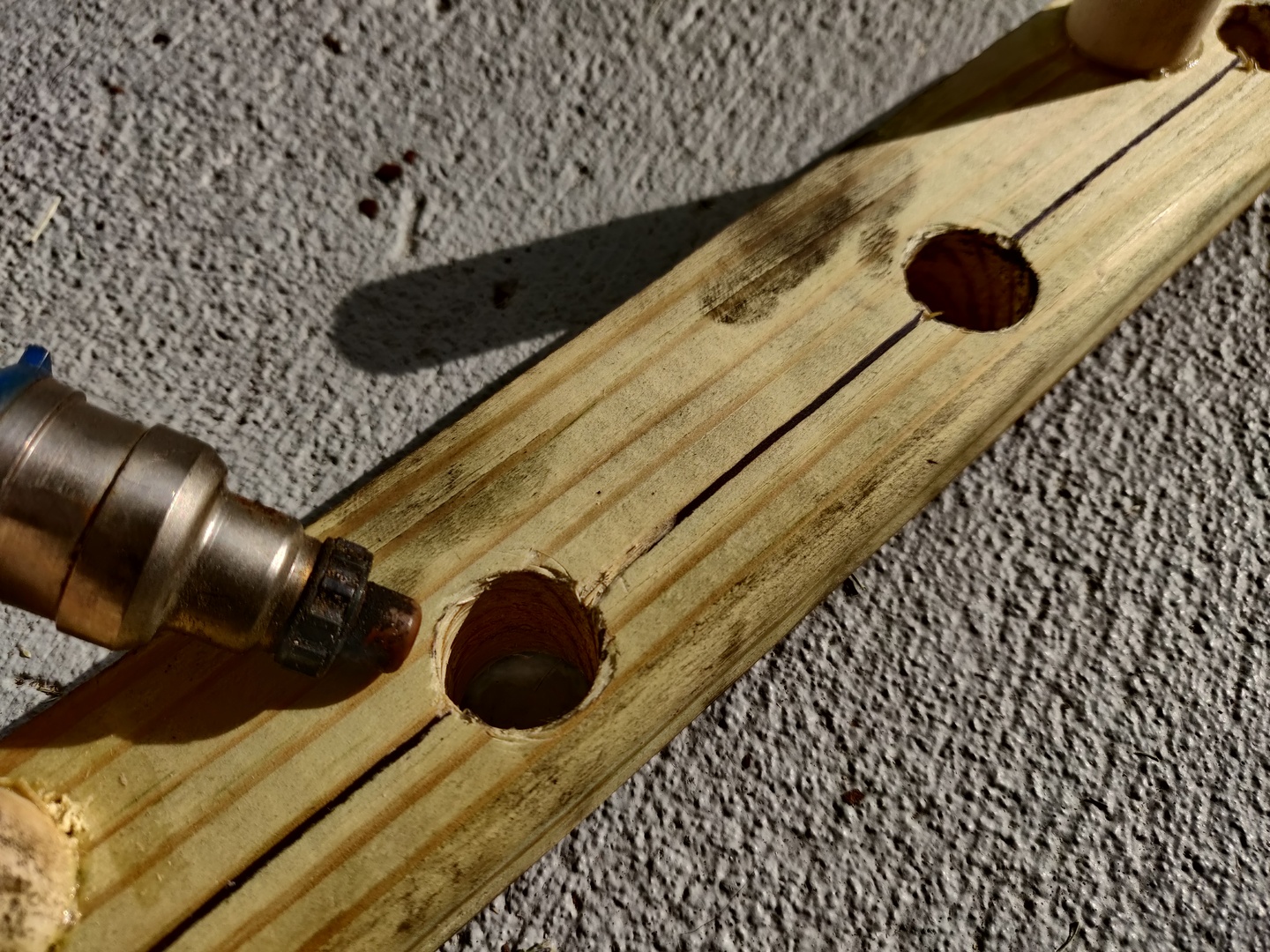
Next, I needed to cut some dowel rods that allowed the fuel rail to be screwed into the jig. The height of the dowel rods needs to be just right so that when the rail is screwed in, it won’t put too much stress on the injectors. What I did was cut the dowels slightly longer than necessary, and then I drilled their mounting holes deeper until the height was just right. Once the height of the dowel was good, I glued them in.
Tuner Studio Injector Test Mode
We’ll need a way to run the fuel pump and pulse the injectors in a controlled manner. The Megasquirt family of ECUs have a test mode that lets you control the necessary functionality through Tuner Studio. The screenshots I captured are from a Megasquirt ECU running ms2-extra-3.4.4, and Tuner Studio v3.1.08. Hopefully the dialogs aren’t that much different between versions.
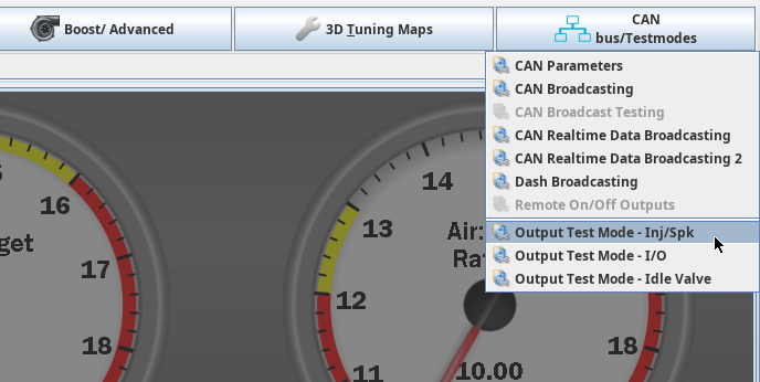
To access the injector test dialog, go to the “CAN bus/Testmodes” menu and select “Output Test Mode - Inj/Spk”.
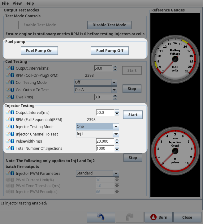
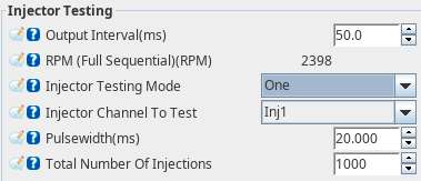
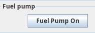
The injector test dialog will open. You’ll need to press the “Enable Test Mode” button before any of the fields are clickable. We’ll be using the “Fuel Pump” and “Injector Testing” sections of the dialog.
Computing Test Parameters
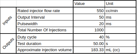
I made a spreadsheet calculator that helps with picking injector test parameters for a given injector flow rate. You enter your injector flow rate and it lets you play with injector test parameters to see things like: how long the test will be, injector duty cycle, and approximate injected volume of fuel. The math is pretty trivial, but it’s a helpful tool to figure out what to expect for each test case.
Injector Channel Control
The test dialog lets you control which injector will fire via the ‘Injector Test Mode’ and ‘Injector Channel to Test’. I found it easiest to leave the ‘Injector Test Mode’ set to ‘All’, and I would physically connect only the injector I was currently testing, leaving the rest of the injectors disconnected from the harness. This approach is pretty much a necessity if your system runs “batch fired” injection, meaning pairs of injectors fire together. If you didn’t physically disconnect injectors then you’d be spraying fuel on two (or more) injectors per test case. The 1990 miatas run batch fired injection.
Test Setup
Bear with me, I didn’t take many photos of my actual setup, so I’ll do my best to explain everything. We’ll be performing the injector tests on the vehicle itself, so pull the car into the garage or wherever is most convenient. This is also a good time to mention that WE’RE PLAYING WITH FUEL, so it’s probably a good idea to keep a fire extinguisher nearby. Consider yourself warned!!!
You’ll want to start by removing the fuel rail from the engine and installing it into the test jig we made. I used wood screws and washers, instead of the original bolts, to mount the fuel rail into the jig. On my setup (not OEM mazda stuff), the wiring harness and fuel lines were long enough to let me position the jig high enough where I could place a container underneath to collect fuel while testing.
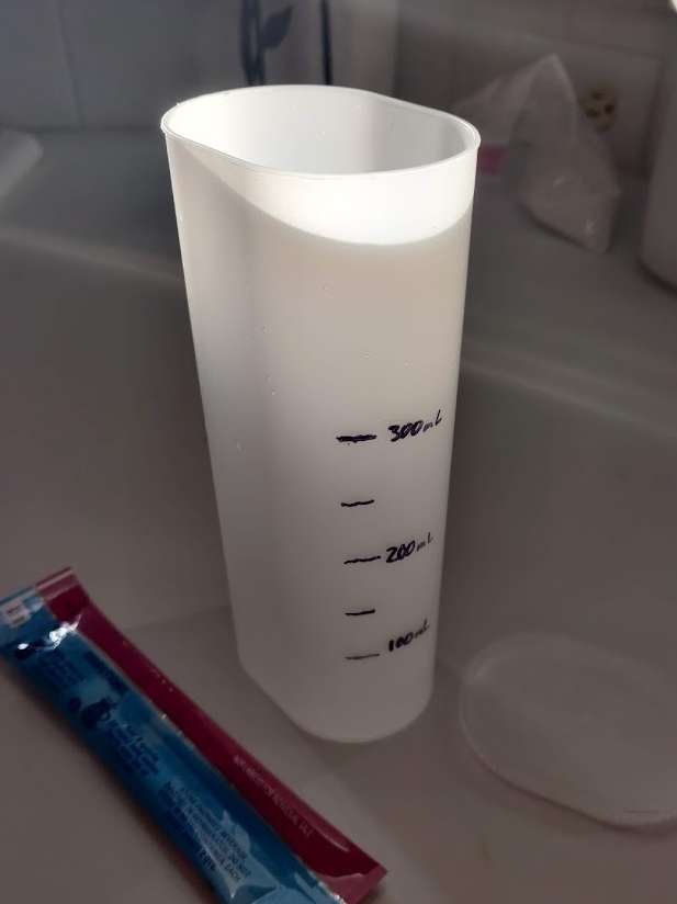
The container you use should probably not be something you eat or drink out of (again… we’re playing with fuel). You’ll want to use a clear container so that you can easily see the fuel level inside. I chose to use a plastic powdered drink mix container because it’s compact and still holds a decent volume of fluid. I also chose to add some graduation marks to help me measure the volume of fuel injected. The graduation marks aren’t necessary if you just plan on making relative measurements between cylinders. In my case, I was mostly interested in the relative comparison, but I also found that you can get some interesting data if you have the absolute volumes measured too (more on that later). If you have a kitchen scale, you can add water in increments of 50mL and mark each line with a sharpie. If you don’t have a kitchen scale, but have measuring cups, then a 1/2cup of water is ~118mL. The reason we use mL for a unit of measure is because injector flow rates are typically in cc/min, and 1mL of water is equal to 1cc.
I’d suggest putting your car on a battery charger while conducting the tests. We won’t be able to run the car, and maintaining constant system voltage is critical to getting good results. You might be able to get by if you have a beefy battery, but I found that my miata’s tractor battery (yes I said tractor) couldn’t keep up over the duration of the test.
You’ll want your laptop connected up to your ECU. It’s nice if you can get a long enough USB cable that will let you have your laptop in the engine bay while running the tests. If you don’t have a long enough USB, then you’ll probably need a buddy with you to hold the test jig in place while you click the buttons on the laptop.
Lastly, it’s good to have pen and paper around to write down notes and results. I also used masking tape to mark the fuel level on the container between tests.
Test Procedure
With all the setup complete, it’s now time to actually perform the tests on each cylinder.
- Turn on the ignition
- Connect Tuner Studio to the ECU
- Open the injector test mode dialog (see section above)
- Enable test mode
- Setup the injector testing parameters for the injector under test
- See section above on computing good test parameters and injector channel control
- Enable the fuel pump
- You should hear fuel flowing through the rail now. Make sure nothing is leaking.
- Place the empty collection container under the injector
- Press “Start” to begin running the fuel injector
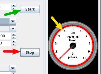
- If you want to stop the test early, you click “Stop”.
- You can see test progress by looking at the “Injection Counter” gauge. It should start at the number of cycles you entered and countdown to zero.
- Once the test completes, the injector should stop firing.
- Disable the fuel pump
- Remove the collection container and place it on a level surface. Mark where the fuel level is and which cylinder it was.
- Once you’ve recorded the results for that test, you can dump the fuel back into your tank.
- Repeat steps 5 through 11 for the remaining injectors you want to test.
- Once you’re done with all the injectors, you can shut off the ignition.

Analyzing The Results
Now for the part that I’ve been waiting for! I ran two sets of tests; one where I ran the injectors at a 20ms pulse width, and another at 5ms pulse width. Testing at two different pulse widths allows you to approximate a parameter called ‘injector dead time’. Fuel injectors are mechanical devices, and they don’t instantly open and close. There’s usually a small amount of time at the beginning and end of the pulse where the injector isn’t really spraying fuel. ‘Injector dead time’ is a simple parameter that is used to characterize this “useless” time within the pulse width.
Test 1: 20ms pulse width; 1000 cycles
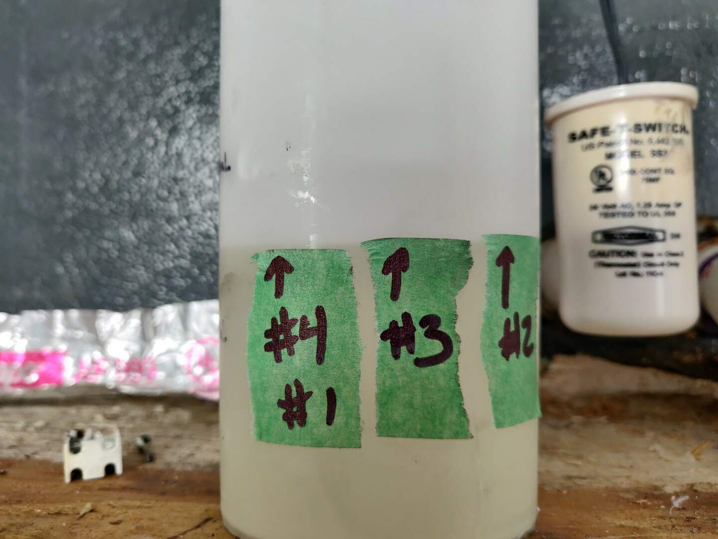
As you can see, all the injectors are spraying relatively equal amounts of fuel; ~167mL total. It looks like there’s about a 10mL spread across them all. I was mostly interested in seeing how cylinder #4 compared to the rest. While cylinder #4 is flowing less fuel than the mean, I was shocked to see that it’s flowing similar to cylinder #1. In my spark plug readings, cylinder #1 and cylinder #4 are drastically different from one another! Makes me think the fouling issues on #4 aren’t fueling related… darn!
Test 2: 5ms pulse width; 4000 cycles
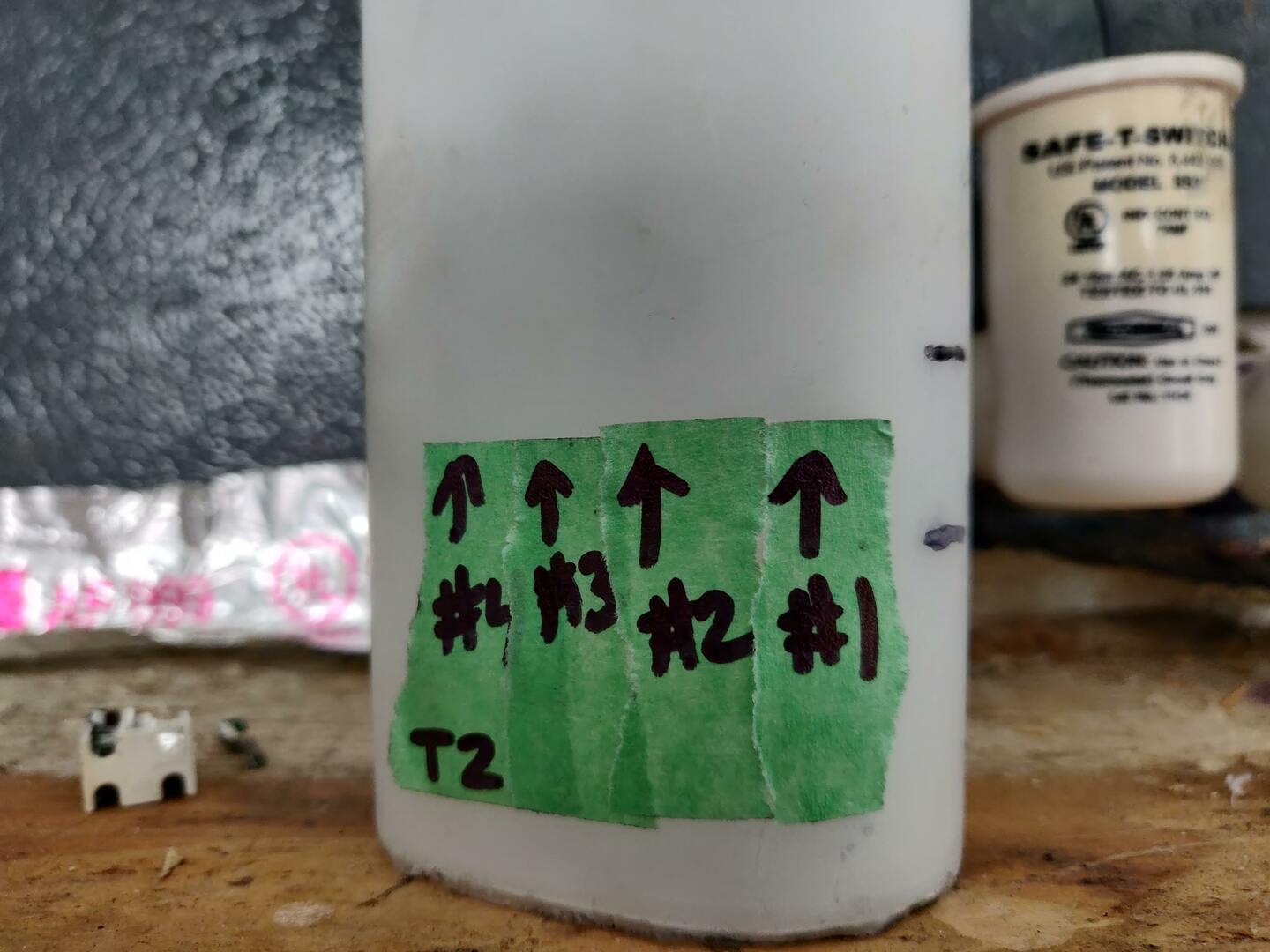
This test shows that the injectors are still spraying relatively equal amounts of fuel; ~130mL total. I was originally shocked that the total volume went down when compared to test 1, even though the total “ON duration” was the same between test cases. I think this is because the injector dead time is now consuming a larger percentage of the overall “ON duration”. After all, injector dead time is the overhead time it takes to open/close the injector; if we increase the number of cycles then we’ll end up with more useless time spent not spraying fuel.
In this test, the spread between cylinders is slightly tighter than the first test. That’s probably ok, considering we’re spraying less total fuel in this test.
The overall profile of the injectors is comparable to test 1; cylinder #2 flows the most and the rest are a little below it. I think this shows that the measurements are somewhat precise and reproducible.
Computing Injector Dead-Time
I tried to find an image online that depicts injector dead-time, but struggled to find one, I drew my own. I’m not sure how accurate my picture is, but I think it gets the concept across.
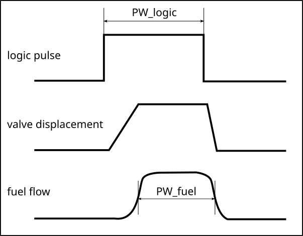
‘logic pulse’ is the signal driven by the ECU. ‘PW_logic’ is equivalent to the pulse width parameter in the fuel injector test dialog. ‘PW_fuel’ represents the realized pulse width when observing the fuel flow out of the injector. You can see that the ‘PW_fuel’ ends up being slightly shorter than the commanded ‘PW_logic’ value from the ECU. The delta between the two is what we call “injector dead-time”. We can write an equation for the injector dead-time (d).
d = PW_logic - PW_fuel
We can also write an equation for total fuel volume sprayed by a fuel injector during each test.
V = PW_fuel * R * C
- V: total fuel volume sprayed in cc
- PW_fuel: observed pulse width duration in ms
- R: fuel flow rate in cc/ms
- C: injector cycles
If we solve our injector dead-time equation for ‘PW_Fuel’ and substitute that into the fuel volume equation, we get the following.
V = (PW_logic - d) * R * C
If I substitute in my values for V, PW_logic, and C for my two test cases I get the following system of equations.
Test 1: 167 = (20 - d) * R * 1000
Test 2: 130 = (5 - d) * R * 4000
If you solve that system, you get d = 1.37ms and R = 538cc/min.
I can believe the injector dead-time of 1.37ms, that seems on-par with what people say these RX7 injectors should run. In my tune, I currently have the dead-time set to 1.25ms @ 13.2V. When I was running these tests, my battery voltage measured ~11.4V even though I had it on the battery charger. I think the dead time is supposed to be higher as the battery voltage drops.
The flow rate of 538cc/min @ 43psi base pressure is also pretty on par. These are 550cc/min RX7 injectors, and I think that pretty close. I’m not sure what pressure the mazda speced the injectors at.
Final Thoughts
Overall, this experiment was pretty fun to do. I didn’t end up finding a smoking gun for my #4 spark plug fouling issue. I guess I’ll need to keep looking. At this point, I’m not sure what else I can look at. I guess maybe EGT temperatures? Not sure what that would say.
Load Comments